Rebuilding the Wires
This summer Jane Street put out a puzzle: here is the physical layout of a small chip, as a GDS file, plus a waveform of some example inputs. Work out what input sequence makes the chip assert its output. Submissions closed on September 4. Jane Street's results post named my submission among their favourite solutions. They wrote to me that they "enjoyed the creativity and thought that went into your approach and writeup".
This post walks through the toolkit I built for it, one stage at a time, in the order data flows through it: layout, extraction, audit, structure, solving, replay. Jane Street asked people not to feed the puzzle files to AI tools during the contest, so the toolkit was built and tested against the warm-up design they published alongside it. Now that the results and the answer are public, I reran the whole pipeline on puzzle.gds to make the figures here. Every number about the puzzle below comes from that rerun.
The layout
The puzzle chip's core is about 200 by 300 microns of SKY130 standard cells. The toolkit's first stage lists the cell types and layers and checks that every cell has a model. On the puzzle it finds 68 distinct functional cell types and 728 functional instances, 92 of them flops, plus 36 annotation-only cells on layer 200/0 that carry no signal and are ignored. The interface is one data input I, clk, rst_n, enable, an 8-bit output O and success.
Placed-and-routed designs tend to keep each RTL module in its own cluster of cells. Grouping cell positions by distance gives about a dozen islands. The labels below come from the toolkit's reports and from a probe I describe in the structure section, checked against the description in Jane Street's results post.
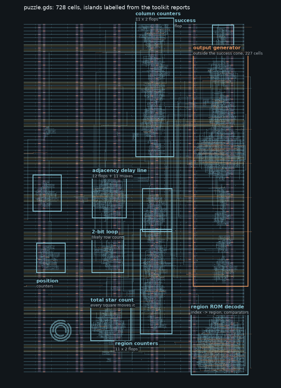
success: the output generator.The gates survive
A GDS file is polygons on numbered layers. If that were all it held, recovering logic would mean finding transistors, grouping them into gates and guessing what each gate does.
A layout from a modern flow mostly keeps more than that. The standard-cell hierarchy survives. Each gate is a named reference to a cell in the SKY130 library (sky130_fd_sc_hd__nand2_2 and so on), placed at a position and orientation, and each cell carries its pin names as text labels on li1. So the toolkit gets every instance and its type for free. What it has to rebuild is which pin connects to which. That reduces the problem to one geometric question: rebuild the wiring.
Extraction: union-find over via centres
SKY130 routes on six conductor layers (li1, met1 to met5) joined by five kinds of cut (mcon, via, via2, via3, via4). The extractor flattens each conductor layer and merges its shapes, so after merging, one polygon is one connected piece of metal on that layer. Layers connect only through cuts. A cut is enclosed by the metal above and below it, by design rule, so its centre point falls inside exactly one polygon on each side. That gives an edge between two (layer, polygon) nodes. Union-find over all those edges gives the nets. Pin labels are then looked up by point on li1.
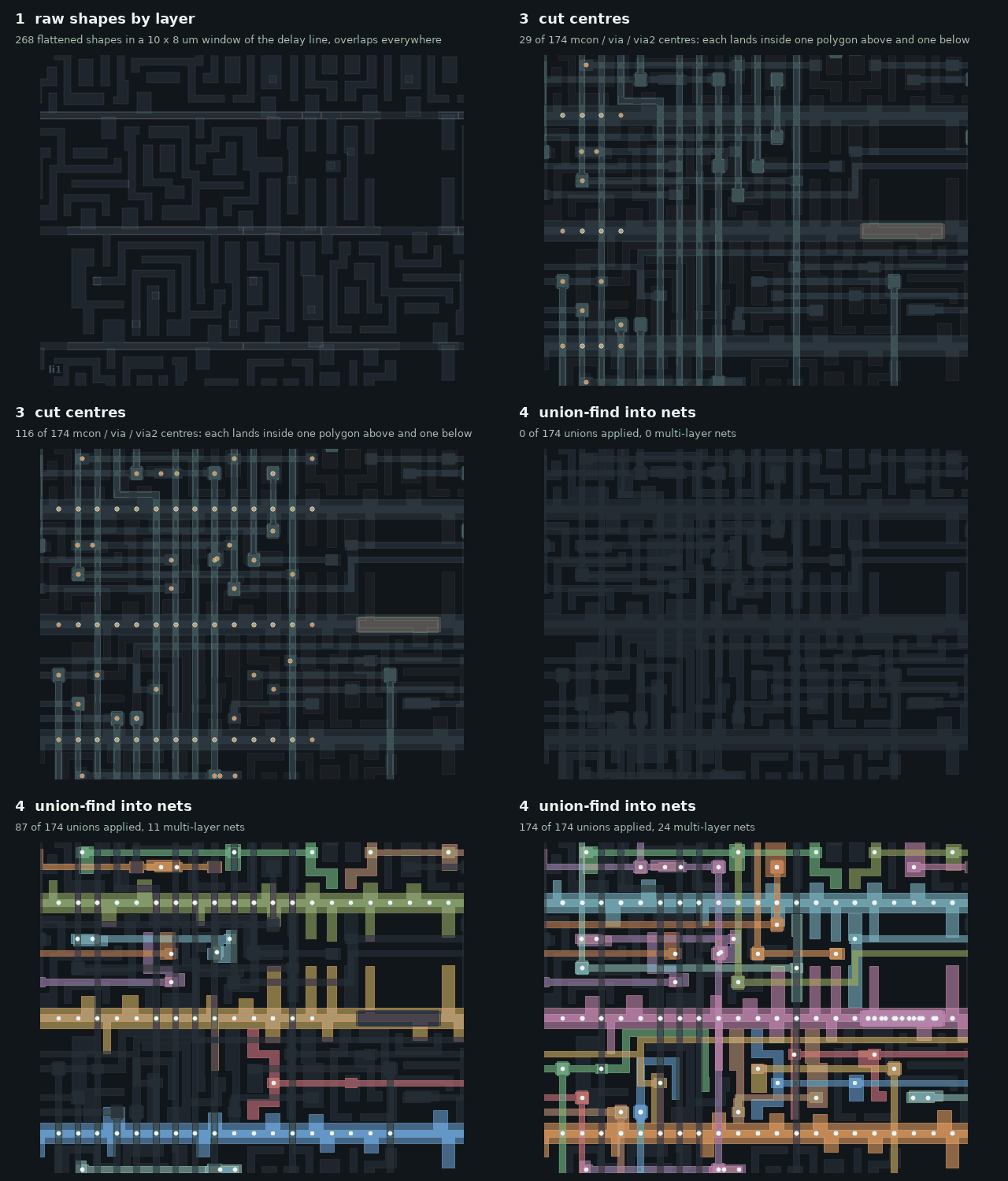
The extractor never computes an intersection between two polygons, which is why the result is clean. On the puzzle, the merged layers come to 6,680 li1, 3,001 met1, 2,060 met2, 811 met3, 45 met4 and 18 met5 polygons. All 27,241 cuts resolve (13,682 mcon, 6,869 via, 3,423 via2, 3,159 via3, 108 via4), with zero unresolved pins. The result is 739 nets. The whole pipeline, including the reports below, runs in 11.9 seconds. On the warm-up there are 3,469 cuts and all 3,469 resolve.
Two smaller things matter. A signal pin that lands on VPWR or VGND is a tie-off. It has to be treated as a constant, or it shows up as a free primary input the solver can set however it likes. And a cell can be placed in eight orientations, so a pin coordinate has to go through the right transform. I checked all eight against an affine transform written from scratch, without calling klayout again.
Validation: extraction fails quietly
If extraction misses one via, nothing crashes. One net becomes two. The circuit still builds, still simulates, and the solver still returns answers. They are answers for a different chip.
So most of the code is about not being fooled. A validator runs 17 structural invariants over the netlist and returns PASS, WARN or FAIL: every net has one driver, every cut resolved, every pin's labels agree on one net, no unmodelled cell types. I built twelve deliberately broken layouts (a missing via, an open trunk, a short between two driven nets, a duplicated port label) and checked that each one was either extracted correctly or flagged. Writing those found bugs in the test harness itself. The "accidental short" case drew its bridge outside both wires, so it shorted nothing and passed for no reason. The synthetic router contacted pins at their label point, which shorted neighbours and made a correct extractor look broken in 16 of 32 orientation cases.
The warm-up came with ground truth at every stage: source Verilog, gate-level netlist, DEF and GDS. The extracted netlist is structurally isomorphic to Jane Street's gate-level netlist, with all 79 cells uniquely matched, and it agrees with the source Verilog on 315 vectors.
On the puzzle the verdict is WARN, for two reasons. 21 driven nets have no sink: 15 are dead logic and 6 are the unused second output of a multi-output cell. And one net, n691, drives two inputs (an a31oi and an a311o) but has no driver. The diagnostics stage traces it and reports that it sits only in the output generator's cone and cannot reach success. The clock trace finds all 92 flops on one clock source through two buffer levels.
Audit: checks that share a source
Every cell is defined once, as a function, and that one definition is evaluated three ways: with booleans for simulation, with Z3 terms for solving, and as Verilog strings for export. They can never disagree with each other. For a while I counted their agreement as evidence.
That agreement proves the engines match. It says nothing about whether the definitions describe the real cells. If or4b is wrong in the model, it is wrong in the simulator, the solver and the export together, and every test passes.
So I wrote an audit that checks every supported cell against the SkyWater Liberty files from the PDK: exhaustive truth tables for combinational cells, and full transition tables plus clock edge and clear/preset polarity for flops. 149 of 149 cells now match. Before they did, it found these:
| Bug | Effect | In puzzle.gds |
|---|---|---|
| or/nor "b" family had the inverted input on the leading pins (SKY130 puts it on the trailing pins for or/nor, leading for and/nand) | silent wrong logic | 18 cells |
xnor3 output named Y; it is X | wrong pin name | 0 |
fah carry-in named CIN; it is CI | wrong pin name | 0 |
| scan flops applied enable after scan in the simulator; Liberty says scan wins | silent wrong state | 0 |
| same order bug in the Verilog emitter | silent wrong export | 0 |
| latches simulated as edge-triggered, falling-edge flops never captured | silent wrong state, now refused | 0 |
The warm-up contains none of these cells, so the warm-up tests could never have caught them. Four of the six were invisible to the earlier suite because it compared the toolkit against itself. The first one matters for the puzzle: it uses 9 or4b, 5 nor3b, 2 nor4b, 1 or3b and 1 or4bb. With the old model, those 18 gates would have computed the wrong function and every internal check would still have passed. Latches, falling-edge flops, tristate cells and integrated clock gates are now hard failures rather than models I cannot verify.
Structure: what the detectors find
The structural report runs a set of detectors over the netlist: shift chains, counters, comparators, adders, mux banks, decoders and repeated motifs, plus a sequential cone analysis from the target output. On the puzzle it says:
- 79 of 92 flops can reach
success. 244 cells and 13 flops cannot, and their bounding box is the right-hand island. That is the output generator candidate. Ifeeds 58 flops andenablefeeds 85.rst_nresets 88.- A 9-flop feedback loop on the left edge and an 8-flop loop in the output island. Eight of the 9-flop loop's outputs are the inputs of the decoders the report lists, whose outputs fan out across the chip. That is what a position counter looks like.
- No shift chain. The delay line shows up instead as a 12-wide mux bank on one select net (
n9, fanout 82) next to a motif of 11mux2_1and 11dfrtpcells. - 25 narrow comparators, most packed in the bottom-right island, and a 13-cell carry chain.
- Two motifs of 14
dfrtpflops each at a 0.92 micron pitch in the centre column.
The counter detector was the weak one. It lumped all 92 flops into one "counter_like" group, which says nothing. To split them I added a probe for this page, close to the impulse method one solver used in the results post: feed a single star at one square, run the 121 enable cycles, and record which flops differ from the all-empty run. Grouping flops by the set of squares that move them separates the design cleanly. Eleven groups respond to exactly one column (squares 0, 11, 22, and so on). Eleven more respond to sets of 14, 21, 7, 5, 28, 8, 11, 9, 6, 8 and 4 squares, which sum to 121 and do not overlap: that is the region map. One flop responds to all 121 squares, the total star count. Twelve flops respond to exactly one square each, the last 12 squares of the board: a star there is still sitting in the delay line when the input ends.
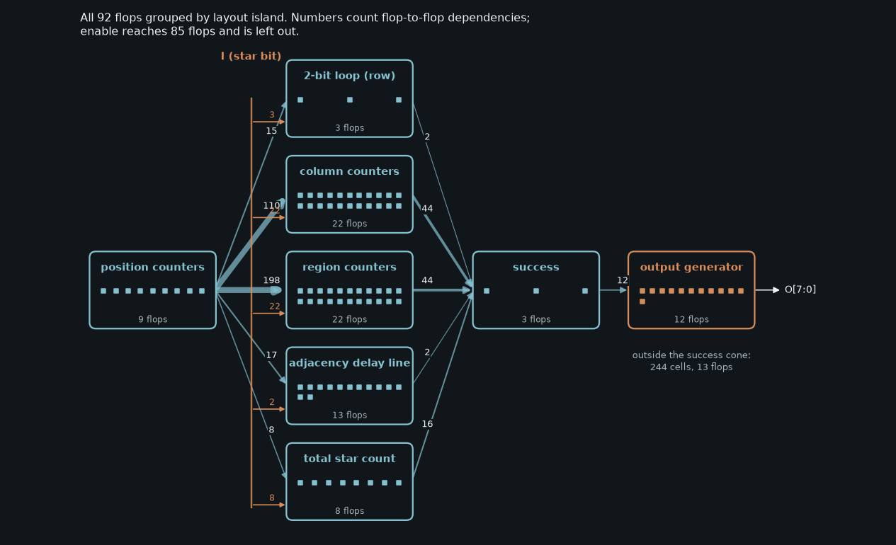
This matches Jane Street's description of the chip: an 11 by 11 Star Battle checker with 2-bit counters per column and per region, a 121-entry region ROM, a delay line for the no-touching rule, and a total-star counter. The row check is the part I could pin down least. The best candidate is a 3-flop island with a 2-flop feedback loop that depends on the position counters, which fits one 2-bit counter reused for each row, but I did not probe it separately.
Solving: bounded model checking
With a trusted netlist, "what inputs make this output go high" is a bounded model checking problem. Unroll the circuit for k clock cycles, make the inputs at each cycle free variables, assert the target, and ask Z3.
The protocol comes from the example waveform. The VCD analyser finds clk with a 10,000 ps period and 312 rising edges, active-low reset, and two enable windows of 121 cycles each (cycles 3 to 123, and again from 159). Replaying both example attempts through the extracted netlist leaves success low, as Jane Street said it should. So the solver holds reset for 3 cycles, drives enable high for 121 cycles and low after, and leaves I free.
Before solving, the reducer cuts the netlist to the cone of success, collapses buffers and folds constants: 728 cells to 467, 92 flops to 79. Each reduction is checked by simulating both netlists on random vectors.
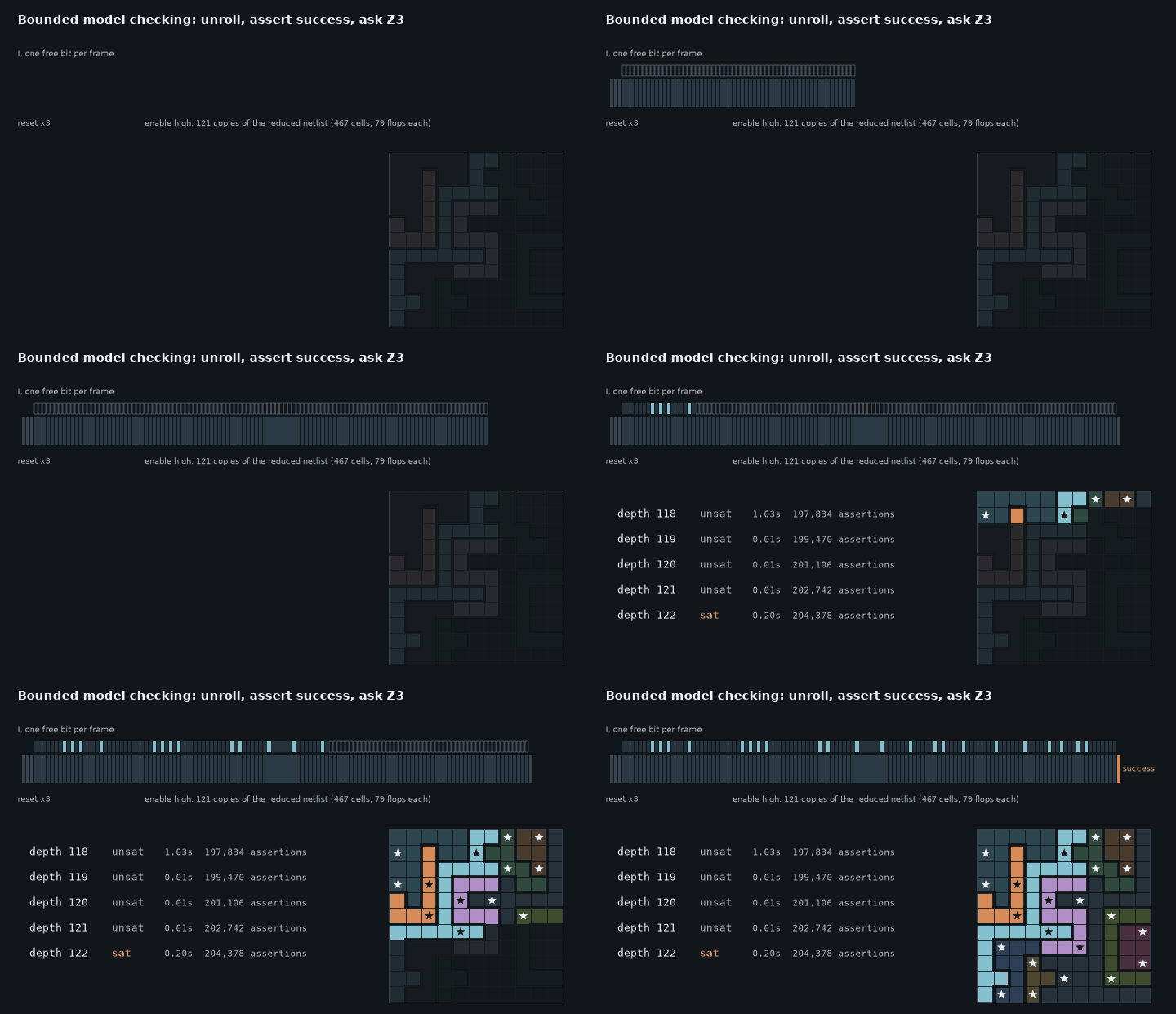
The structural report suggested at least 20 cycles, from the longest flop chain. That bound is right for a shift register, where every bit sits one step from the comparator but the register takes its full length to fill. Here the true bound is set by the protocol instead: the chip needs all 121 squares before it can decide. The solver steps through depths 118 to 122. The first four are unsat in about a second in total, and depth 122 is sat after 204,378 assertions. The full run, including building the unrolled problem, takes 26.4 seconds. The returned model is replayed concretely before it is accepted, and success first goes high at cycle 121.
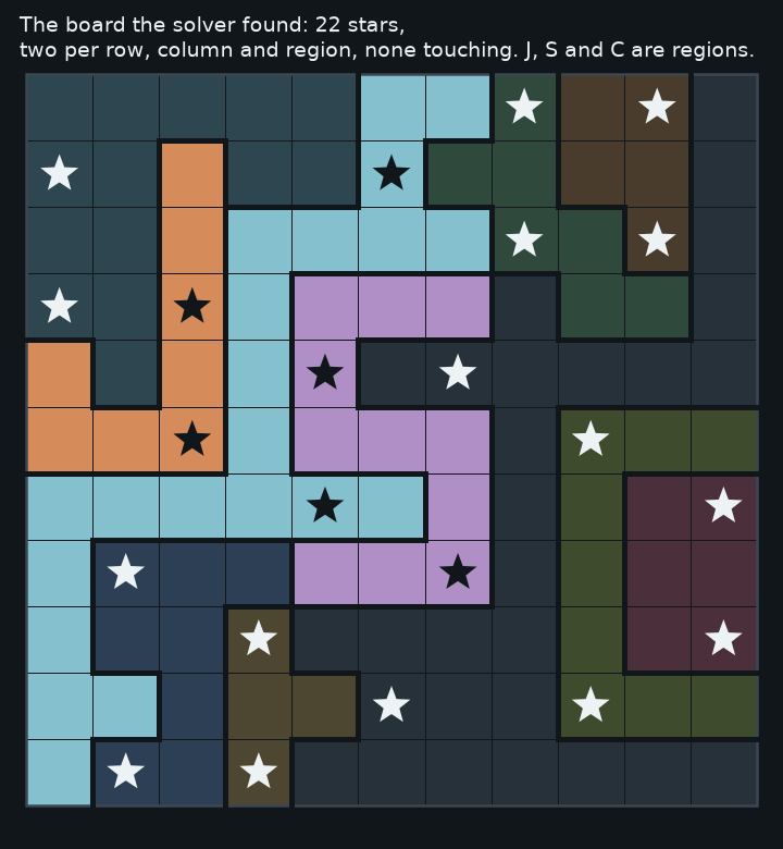
Of the 121 bits, 22 are ones. Read row by row they give a board with two stars in every row, column and region, and no two stars touching.
Replay and the answer
Nothing the solver returns is accepted until it has been replayed through the full, unreduced netlist, including the 244 cells the reducer removed. The replay stage runs the solved inputs, keeps clocking with enable low, and reads O[7:0] as bytes. It also checks the undriven net n691 at both values, and the string comes out the same either way.
![Waveform animation: clk, enable, I and success, then O[7:0] bytes 28 2a 20 54 57 4f 20 53 54 41 52 53 20 2a 29 spelling (* TWO STARS *)](figs/reverse-asic/waveform.gif)
enable drops, success rises, and the output generator emits one byte per clock.The output is 15 bytes: 28 2a 20 54 57 4f 20 53 54 41 52 53 20 2a 29, which is (* TWO STARS *), then zeros. That is the string Jane Street's post gives for a correct board.
How it lines up with Jane Street's favourite approaches
Cell names were left in the GDS, which is the observation the whole extractor rests on. Some solvers used existing LVS tools to pull out a netlist and some wrote their own. Vladislav Shapovalov wrote a C++ extraction pipeline and debugged it on the warm-up before running it on the puzzle. Mine is Python, built the same way, because the warm-up is the only design where every stage has ground truth.
Their main lesson was that a model matching the sample waveform can still be wrong. One solver's Python model reproduced the trace while getting every tie-high cell wrong, which silently disabled the adjacency check. He caught it by comparing against a separate Icarus Verilog simulation on extra inputs. That class of failure is what the Liberty audit, the adversarial layouts and the randomised differential checks are for. Tie-offs are handled explicitly: a pin tied to VPWR or VGND resolves to a constant, and there is a test for each.
The post also says SAT finds an input easily but says little about how the circuit works, and highlights solvers who kept going after the answer. Sanjay Ravishankar used the layout islands as bounding boxes for modules, and Aaron Shi diffed every flop against an all-zeros baseline after single-bit impulses. The structural report and the island labels above are the same idea: the toolkit reports what the circuit counts as well as how to satisfy it.
Along the way I also found some of the Easter eggs Jane Street hid in the layout and waveform.
| Check | Result |
|---|---|
| Cell models vs SkyWater Liberty | 149 of 149 exhaustive, 0 mismatches |
| Test suites | 18 of 18 pass |
| Warm-up extraction | 3,469 cuts resolved, 0 unresolved |
| Warm-up vs gate-level netlist | isomorphic, 79/79 cells matched |
| Warm-up behaviour vs source Verilog | 315 vectors, 0 mismatches |
| Puzzle extraction | 27,241 cuts resolved, 0 unresolved, 739 nets |
| Puzzle solve | sat at depth 122, unsat at 118 to 121 |
| Puzzle replay | (* TWO STARS *), same for both values of n691 |
| Pin transforms | 8 orientations vs independent affine |
| Adversarial layouts | 12 of 12 extracted or caught |
| Sequential semantics | 11 circuits vs independent RTL |
| Randomised differential | 300 circuits, about 3,500 cells |
| BMC soundness | 28 known-answer checks, incl. unsat |
What is still assumed
Some things I could not verify from a second source. Nothing independent tells me the six-layer stack is every conductor in the design, or that every pin label sits on its own shape. If a design routed on a layer I don't model, nets would just look open. So the first stage of the pipeline prints the full layer inventory, and the runbook says to read it rather than skim it. The island labels rest on the probe and on Jane Street's description, and the row counter is the one block I identified only by elimination. I also never got Yosys installed, so the generated Yosys scripts are untested. The SMT2 path is.